Skills Devloped:
- Prototyping / quick iterations
- CAD
- 3D printing
- CNC machining of aluminum
- Electronic installation
During my senior year in high school, I took a capstone project class. In this class, we selected a topic that we wanted to pursue and research. I chose to design and create my own electric longboard. This project gave me the opportunity to learn about various types of motors, batteries, and general electronics. I employed advanced techniques in both CAD software and programming to ensure the skateboard works as planned. This project showcases my creative ability and engineering while also providing me a reason to learn how to longboard.
Initial research and brainstorming:
I have conducted extensive research and prototyping for the E-board. I have decided to use a longboard for maximized stability while riding. I utilized a motor and battery setup that I was able to acquire easily for the initial proof of concept and first prototype. After successfully getting the prototype to work, I planned to purchase the ideal motor, battery, and ESC setup. I based these choices on calculations I performed for my desired top speed and runtime. The main components I need to fabricate for the E-board include the pulley hub mount, motor mounting plate, and battery case.
Wheel Hub
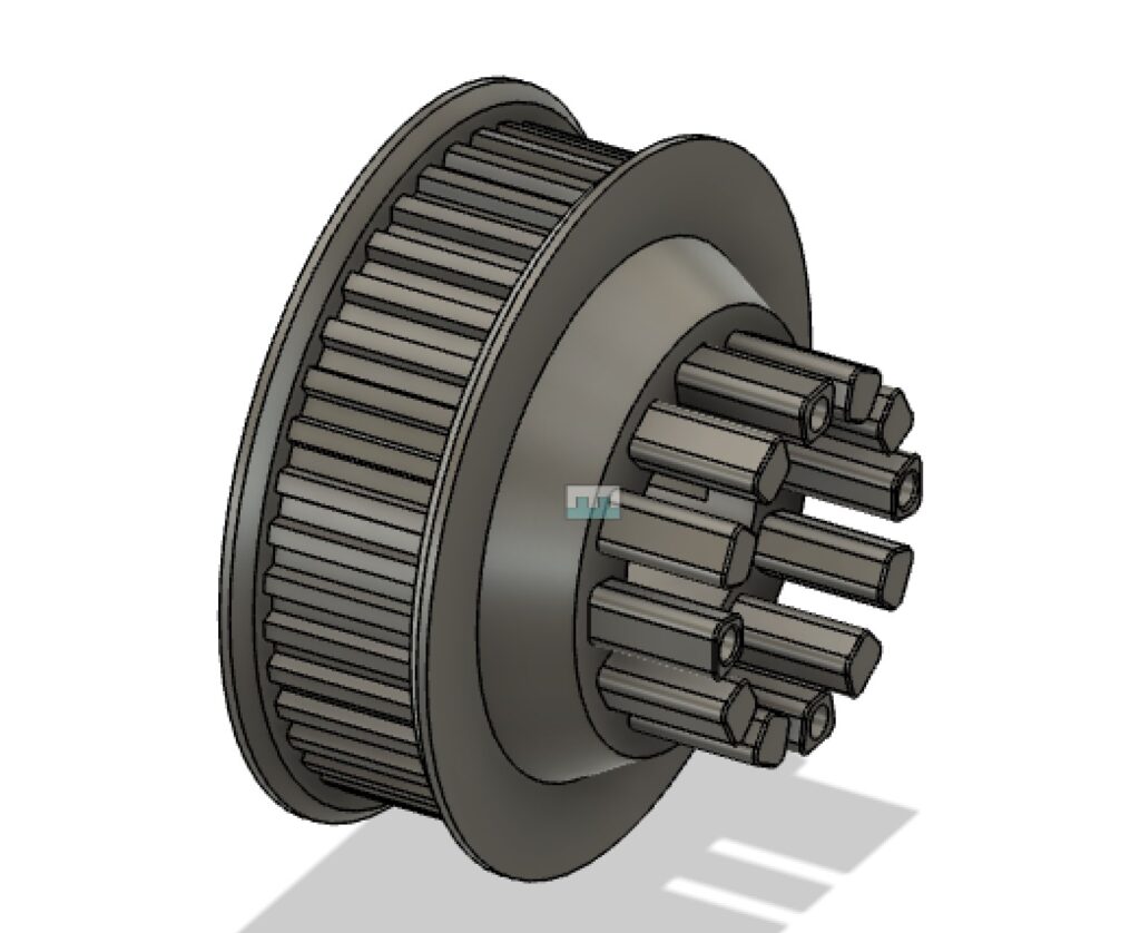
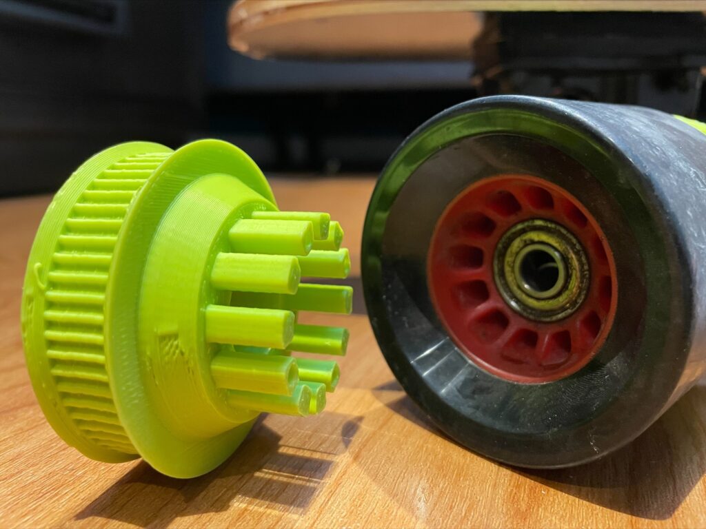
The first component I created was the pulley hub mount. This piece connects a standard longboard wheel to a pulley, allowing the motor to power and propel the board.I chose to power only a single wheel for simplicity. This wouldn’t impact performance due to the short distance between the two rear wheels.
Process: I began by taking measurements of the inner rim of the wheel. This allowed me to create posts on the hub that could slide firmly into the wheel, effectively locking the two components together. Using those measurements, I developed a CAD model of the part. I then obtained the pulley specifications and generated a matching 3D model. This 3D model was attached to the posts that would connect with the longboard wheel.
The final step in the design process was to create four holes that would pass through the entire part. This enabled me to drill matching holes into the wheel itself, allowing four long screws to go through both the wheel and the hub, securely holding the two parts together. After completing the CAD design, I proceeded to 3D print the part and then tested how they fit together.
Motor Mount Plates
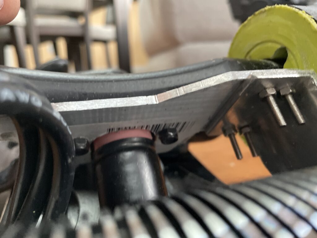
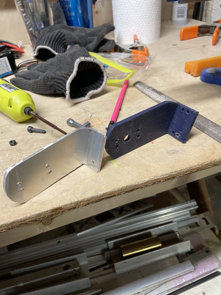
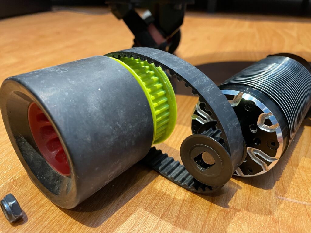
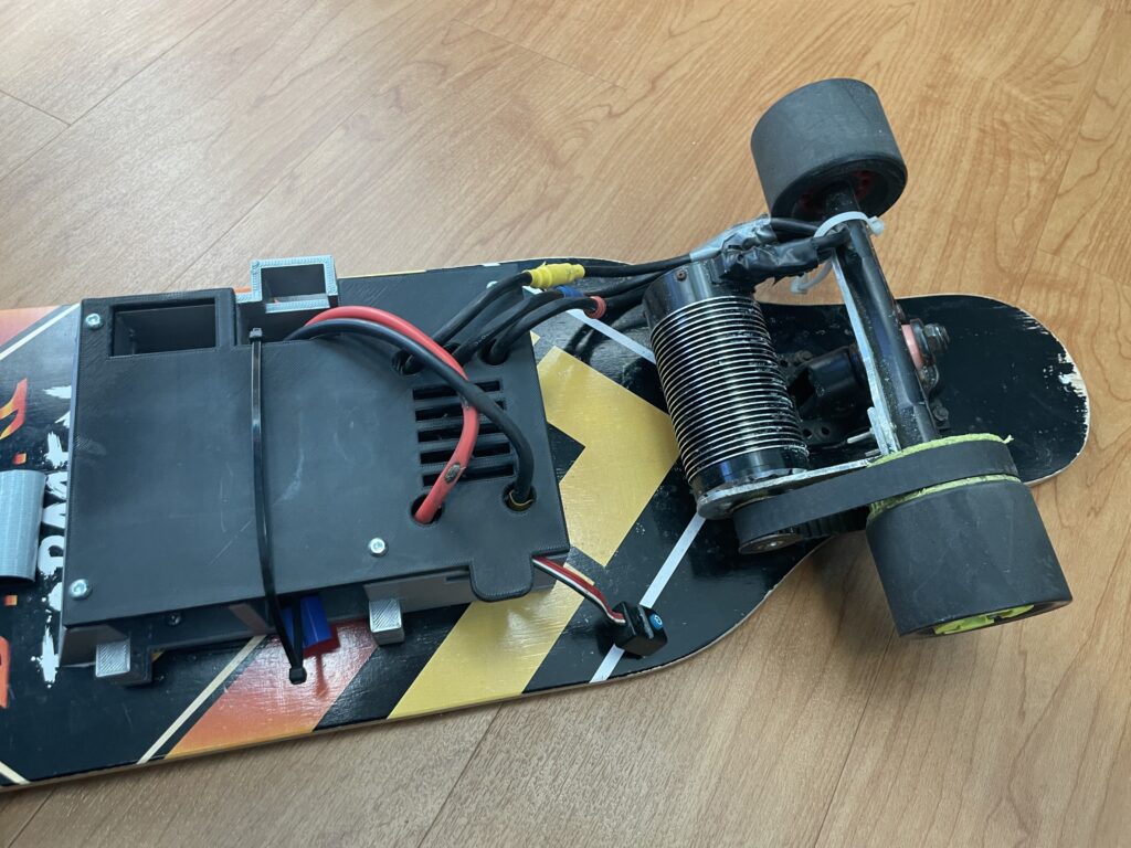
The second component I created was the motor mounting plates. The longboard has two steel trucks where the wheels are mounted. These trucks move with the wheels, while the wooden board moves separately during turns. This distinction is important because the motor must remain relative to the wheel to maintain constant pulley distance. Therefore, the only suitable location for mounting the motor is onto the trucks of the longboard. These trucks were not initially designed for attachments. I designed two custom plates to solve this. The first provided a flat mounting surface on the truck. The second offset the plate by 90 degrees, creating mounting points for the motor.
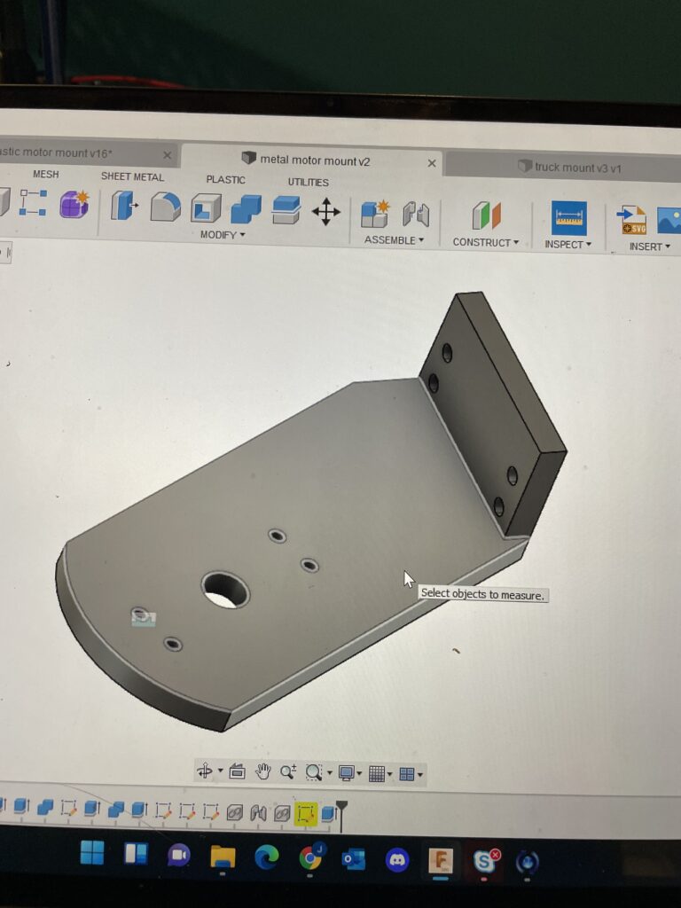
Process: To create the first plate, I took measurements of the truck and analyzed the optimal locations for mounting screws. After completing this step, I then designed a plate conforming to the truck’s shape. I then incorporated holes for mounting into both the truck and the other motor mounting plate. I transferred this design into the Mach 3 software, which was compatible with the Omnio X8-220L CNC machine I had access to. Using this software, I proceeded to cut the piece out.
For the second plate, I measured the required motor distance to accommodate the pulley size. I also determined the offset angle needed to avoid contact with the board during turns. After designing the part in CAD and adding all the necessary mounting holes, I printed a 2D model of my design on paper. I affixed this paper template to the C-channel piece. Using a bandsaw, I cut out the part while following my paper guide. I couldn’t use the CNC machine for this part. The bit mount would collide with the C-channel’s raised sides.
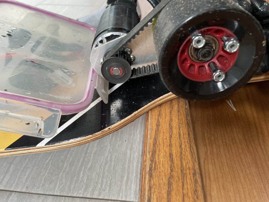
After both parts were cut and refined, I proceeded to install them along with the motor and pulley onto the board.
Electronics Box
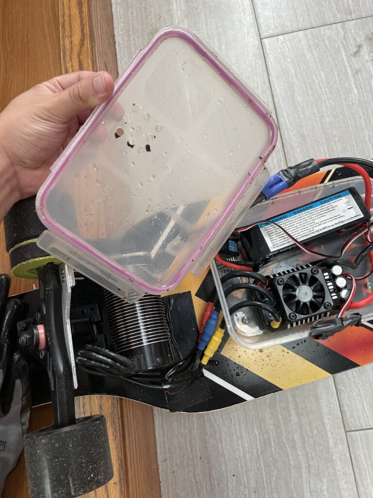
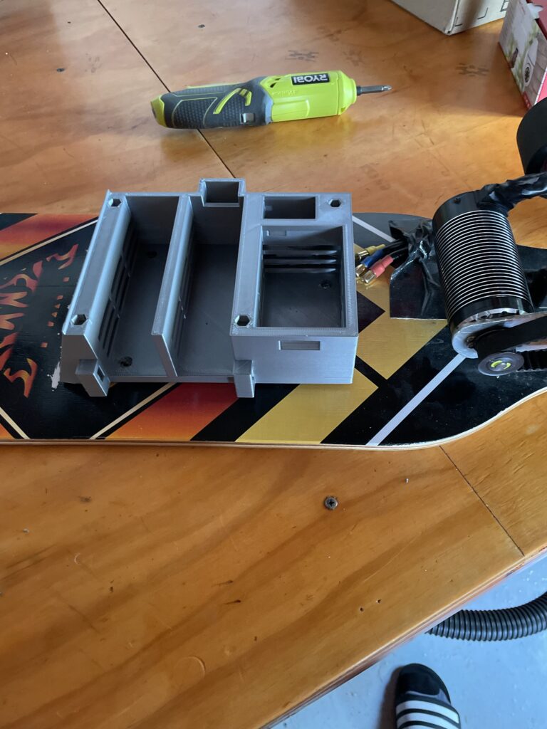
The third component of the longboard was the electronics and the case in which they would be housed. I conducted basic calculations using my Physics 1 knowledge to estimate the motor load. This was essential for finding electronics suitable for the task. I utilized the same electronics found in RC cars: an ESC, receiver, remote, and batteries. These components required a protective case to shield them from environmental conditions.
Testing revealed the case needed effective ventilation to prevent overheating under high loads. This was to ensure that the electronics wouldn’t overheat when subjected to high loads.
Process: Initially, I aimed to test all my electronics before crafting a custom case to accommodate them. I prototyped a case using a plastic storage bin. I affixed the bin to the board using screws and drilled holes for the wires to exit. With the electronics placed inside, I sealed the lid, and I was prepared for testing. After multiple successful tests, I concluded that the chosen electronics were suitable for the task. Subsequently, I turned to CAD to design a case that would more appropriately house the components.
In the case design, I incorporated specific compartments for two batteries, a receiver, and an ESC. I also included a designated area for a voltage reader with a visibility slot for runtime monitoring. After integrating holes for ventilation, wires, and mounting, I produced a 3D printed version of my design. After mounting and testing, the case successfully secured all components. This marked the completion of my electric longboard.