Overview
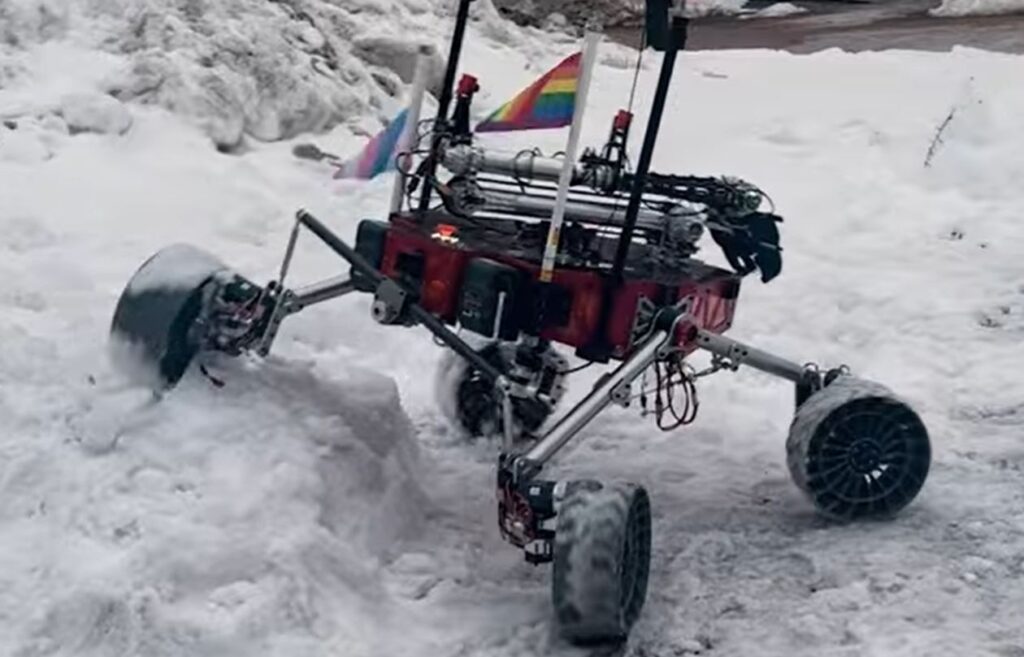
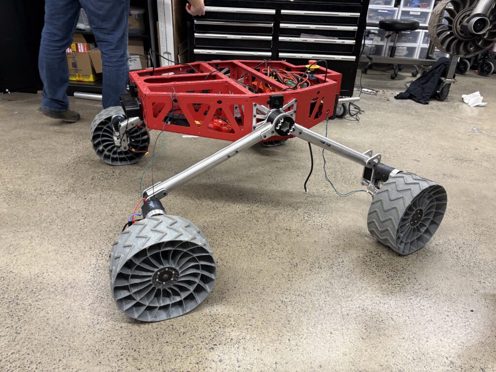
The NU rover team decided to implement a swerve module mobility system this season, which required a new rocker system to mount them. As the mobility team lead, I designed components to mount two rockers on each side and connected them with a differential bar.
Skills developed
- Master modeling
- Material spec and purchasing
- Water jet
- 3D Printing
Rocker
Design Requirements:
- Size constraint(1.2mx1.2m)
- Swerve module ROM clearance
- Off road terrain capable
- Withstand drops up to 2 ft high
- as lightweight as possible
One of the hardest aspects of this challenge was designing the rocker system while other critical dependent components were still not finalized. Most notably the chassis not being completed caused the most issues because it presented a lot of variables in terms of mounting and space restrictions.
Design process
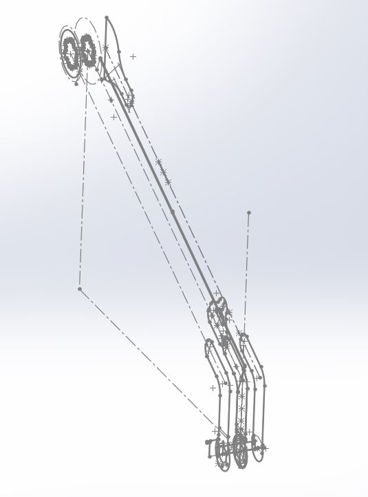
Our first step was to sketch out the overall system as well as the key components. We used these rough dimensions to run some calculations on the strength requirements of the system. With that information we then ordered the stock material.
Due to variability of our mounting requirements we knew that a robust and easily modifiable CAD structure was crucial. We created a master model to allow us to constraint and relate components efficiently allowing for quick and painless adjustments throughout the whole design process. Being able to change variables like ride height, track, and rocker angle gave us a lot of flexibility to accommodate and quickly adjust to various requirements.
Manufacturing and Assembly
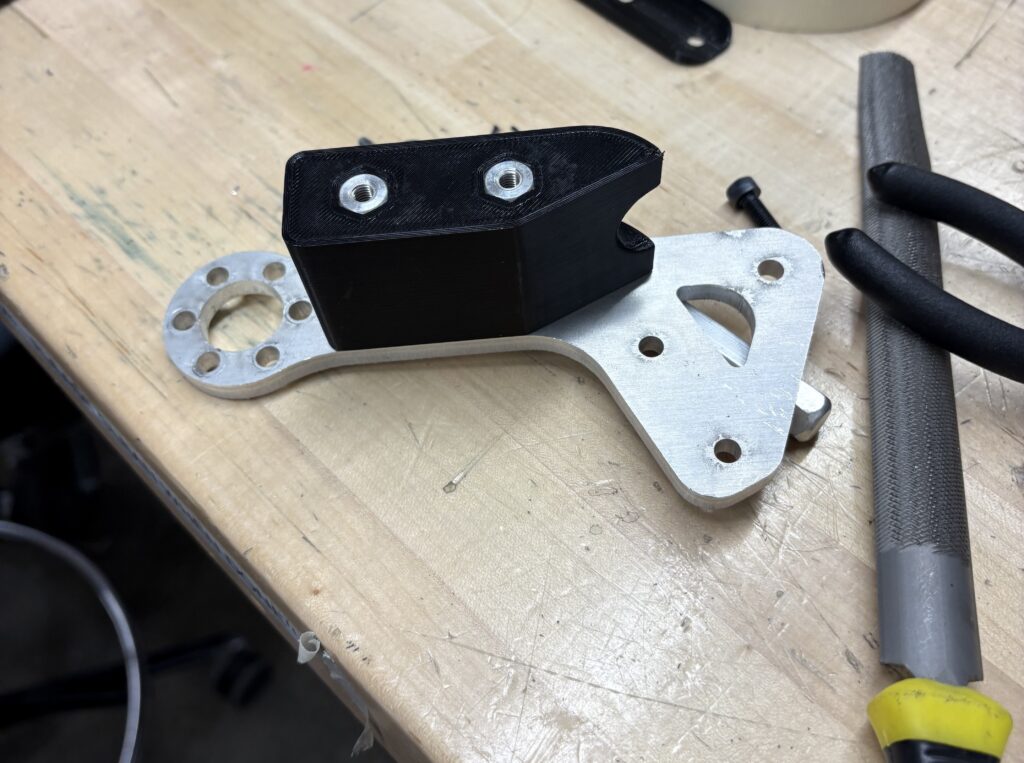
The structure of the rocker is maintained with aluminum parts and then further supported with 3D prints. We cut the aluminum parts using a water jet and ordered any CNC parts. The 3D printed parts were printed using PETG and served an important role in fitting flat parts onto a round central tube as well as helping with wire management.
For precisely drilling holes into the main tube we 3D printed a jig to guide the drill bit also ensuring that the various components were all along the same axis. We also included a tension cable between the two pipes to minimize the moment arm and reduce load at the top axis when driving on rough terrain. We then torqued all screws to spec and used Loctite on all screws to prevent them from rattling out during use.
Diff Bar
Design Requirements:
- Maintain orientation of the chassis while traversing off road terrain
- Do not interfere with ground clearance
- Lightweight
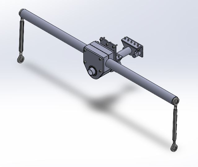
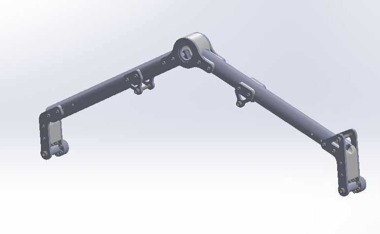
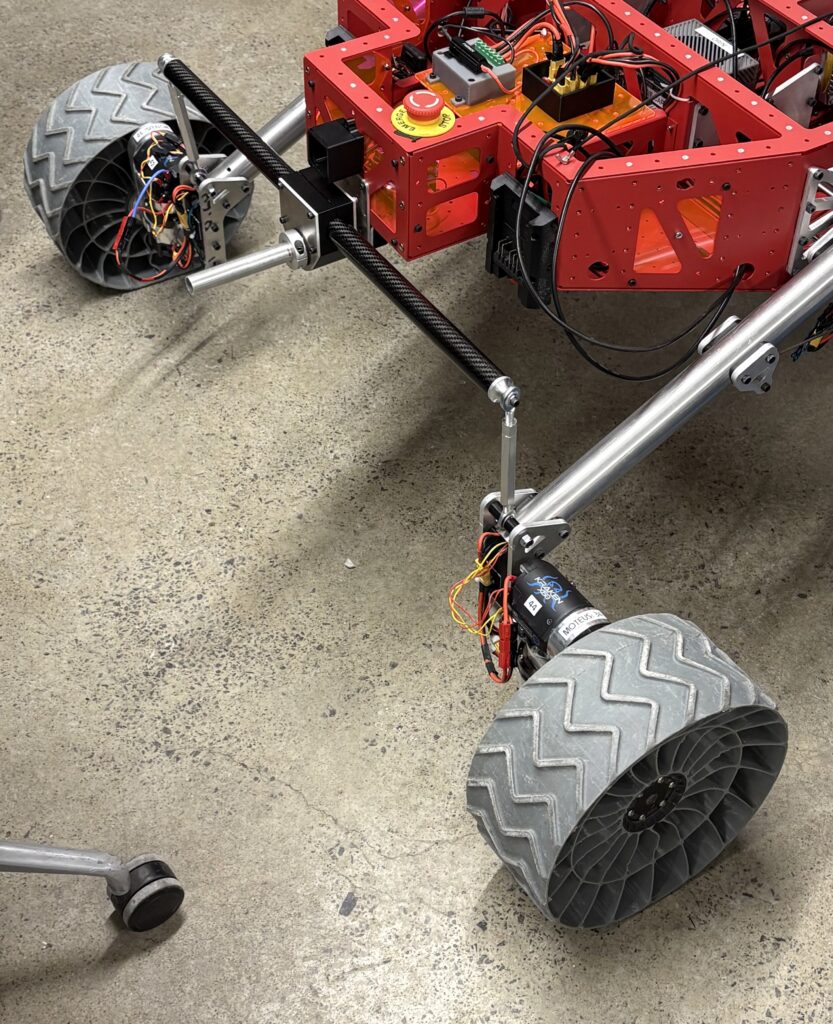
Similar to the rocker we used a master model approach for this component to easily adapt for mounting onto the chassis as well as adjusting to any changes made to the rocker. The design consists of two perpendicular pipes and two turnbuckles connecting the diff bar to the rocker.
The hardest manufacturing challenge for this component was cutting the carbon fiber pipe. To do so safely we used a laser jet. It was also important to have a solid pipe connecting both rockers therefore we used a 3D printed clamp at the center axis. To mount the turnbuckles to the pipe we used a CNC part with ridges to help with firmly gluing the turnbuckle mounts into place.
Steerable Antenna
Design Requirements:
- Mount to the top of the base station tower
- Rotate 360 degrees
- Include sensors for directional awarness
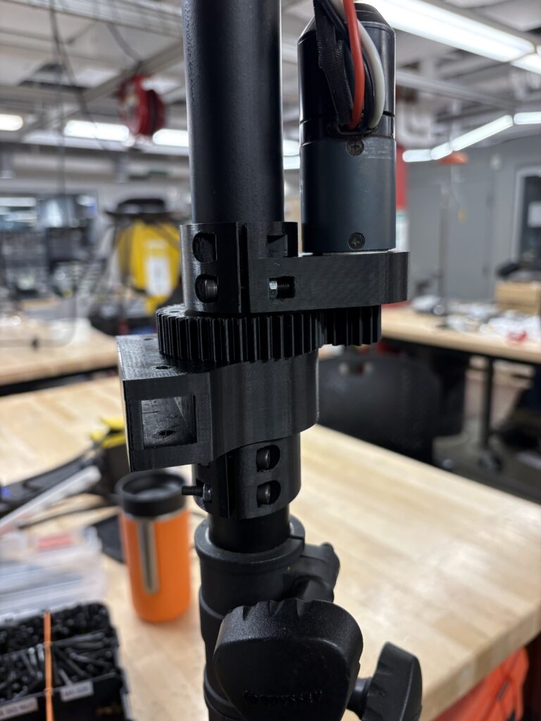
The motor clamp is stationary and when actuated will rotate the antenna mount part beneath it to the correct angle to communicate effectively with the rover.